Custom CNC Machining
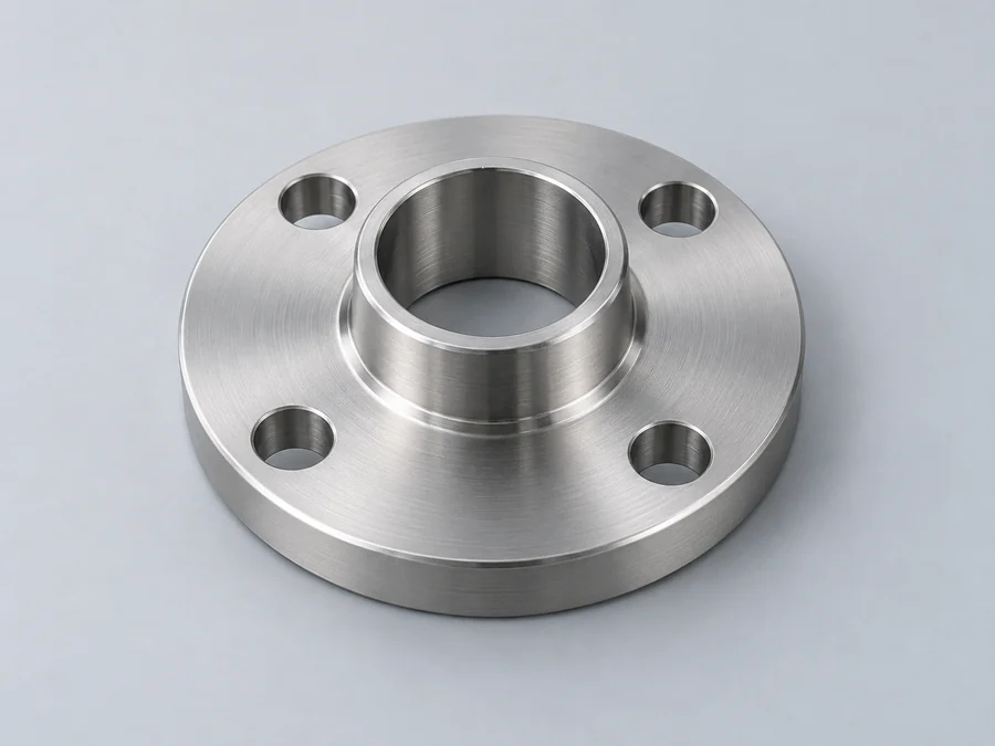
WLZ-FLA-001

Flanges & Adapters

Connect components with matched interfaces.

Made to drawing
CNC milling
Prototype & repeat orders
Part configuration Adapter plates, interface plates, slotted plates
Material starting points Aluminum, stainless steel
Critical features Hole patterns, thickness, flatness
Manufacturing basis Model + drawing + project requirements

DESIGN THE INTERFACES

Two patterns. One plate.

Define the hole sets and thickness that adapt one interface to another.

  • 01 Primary hole set

    Locate the first mounting pattern from a clear datum.

  • 02 Secondary hole set

    Position the mating pattern and any slotted adjustment.

  • 03 Thickness & flatness

    Call out plate thickness and flatness on seating faces.

  • 04 Countersinks & threads

    Define countersinks, threads and edge conditions.

Price, feasibility and lead time are confirmed after reviewing your project.

Feature reference diagram · not a manufacturing drawing

Your drawing is the specification

Define the requirements that matter.

No fixed catalog dimensions. Use these fields to define the part for your assembly — the same CNC inputs apply across all component families.

Specification

Define for your part

Review basis

Envelope

Overall size, usable envelope and any pocket or profile depth that controls the part.

3D model + dimensioned drawing

Walls

Wall sections, bosses, ribs and tool access around deep or narrow features.

Geometry review before quotation

Holes

Hole patterns, slots, thread standard, size, depth and insert requirements.

Explicit callouts on the drawing

Fits

Critical dimensions, datums, mating faces and the interfaces that control assembly.

Feature-specific requirements

Material

Material grade, surface finish, color, cosmetic faces and masked areas.

Suitability and process confirmation

Inspection

Key dimensions, inspection points and required material or inspection documents.

Scope agreed with the quotation

Quantity

Prototype, pilot or repeat quantity, drawing revision and requested delivery date.

Price and lead time confirmed after review

Materials & grades

Materials for CNC components.

Specify the material grade on your drawing. The final choice depends on geometry, operating environment and finish.

01

Aluminum

6061 · 7075 · grade to drawing

For lightweight bodies, plates and parts with a specified anodized finish.

Finish options to specify

02

Stainless Steel

304 · 316 · grade to drawing

For corrosive or clean environments. State cleaning and operating conditions.

Finish options to specify

03

Engineering Plastics

POM · PEEK · material review

For non-metallic requirements. Grade selection depends on temperature, chemical exposure and loading.

Finish options to specify

Surface finishes

Define the surface. Protect the fit.

Identify visible faces, finish specifications and surfaces to mask. Dimensions that matter after finishing should be called out on the drawing.

Include color, roughness and cosmetic requirements where they affect the finished part.

As-machined

Metal & polymer

Specify surface roughness and edge condition where they affect assembly. Tool marks may remain on machined surfaces.

Bead blasted

Metal parts

Define the exterior texture and cosmetic faces. Identify mating faces, threads and other areas that require masking.

Clear or color anodized

Aluminum

State the anodizing specification and color. Call out fit-critical dimensions after coating and any electrical contact areas.

Passivated

Stainless steel

Specify the treatment and cleaning requirements where applicable. Define the required surface condition separately.

Supply scope

Specify what comes with the part.

Define what is included with the machined part in the quotation.

01

Part & mating items

Specify the machined part and any mating covers, plates or sealed interfaces called on the drawing.

02

Threads & hardware

Define thread sizes, inserts and mating hardware. State whether the order covers machined features only or additional assembly.

03

Inspection & protection

Identify critical dimensions and required records. Specify protection for cosmetic faces, threads and mating surfaces during packing.

Product questions

Component FAQs.

Material, assembly and order details that apply across CNC component families.

Include all related drawings or a complete assembly model, and state which parts are required. Fasteners, seals and assembly work should be listed separately so the quotation defines the full supply scope.

Include the material grade, finish specification, color and surfaces to mask. Identify dimensions that must meet the drawing after finishing, particularly fits, threads and electrical contact areas.

Show the insert reference, thread details or seal geometry on the drawing. Hardware installation and sealing requirements are reviewed with the complete assembly; a groove alone does not establish an ingress-protection rating.

Provide the current drawing revision, model, material, finish and required quantity. You can include prototype and repeat quantities together. Feasibility, price and lead time are confirmed after review.

Request a product quote

Your part. Your requirements.

Send your drawing, material, quantity and critical features for a custom CNC quotation.

01

Drawing or 3D model

STEP / STP and a dimensioned PDF, with the current revision.

02

Material, finish & quantity

Include the grade, surface requirements and order quantity.

03

Critical requirements

Note fit-critical features, inspection needs and your target date.

Request a quote

Tell us about your project.

Price, feasibility, lead time and supply scope are confirmed after reviewing your requirements.

错误: Content is protected !!