COMPONENTS IN CONTEXT

Every part starts
with a requirement.

Explore the geometry, interfaces and surface requirements behind different CNC project types.

PROJECT EXAMPLES

Find a requirement
that looks like yours.

Explore housings, mating components and finished brackets through their geometry, assembly interfaces and surface requirements. These are typical application briefs — not named client projects.

3 illustrative project examples

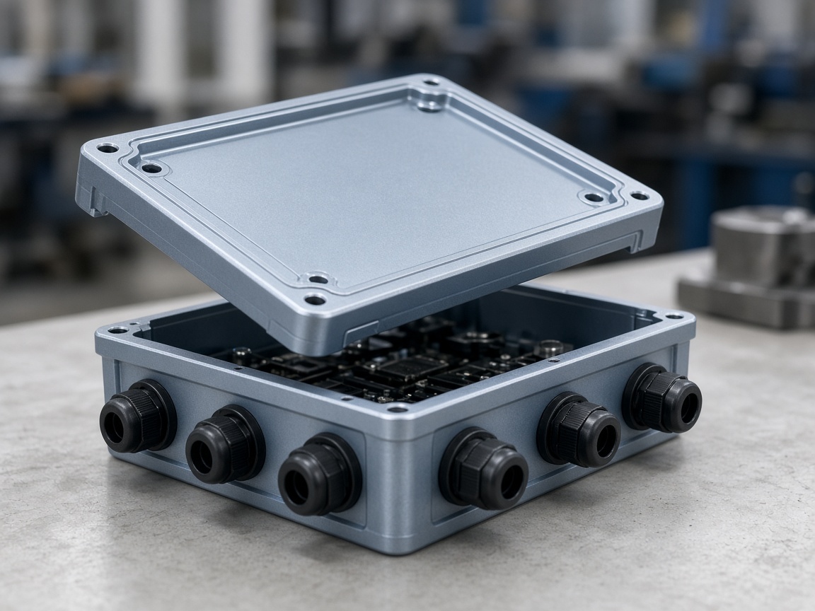
Technician fitting a lid over an instrument enclosure containing electronics and cable connections

01

ILLUSTRATIVE PROJECT

Instrument housing

CNC MILLING

An enclosure with more than one interface.

An internal assembly, an external cover and a mounting surface need to fit one component.

PROJECT FOCUS

Pocket geometry / cover interface / mounting datums

Read Project Brief

+

Starting information

A complete housing model, assembly envelope and a drawing identifying the mounting references.

Review priorities

Review pocket access, internal radii, wall sections and the relationship between the cover and mounting features.

Scope to agree

The agreed housing geometry, material, final surface and specified inspection records.

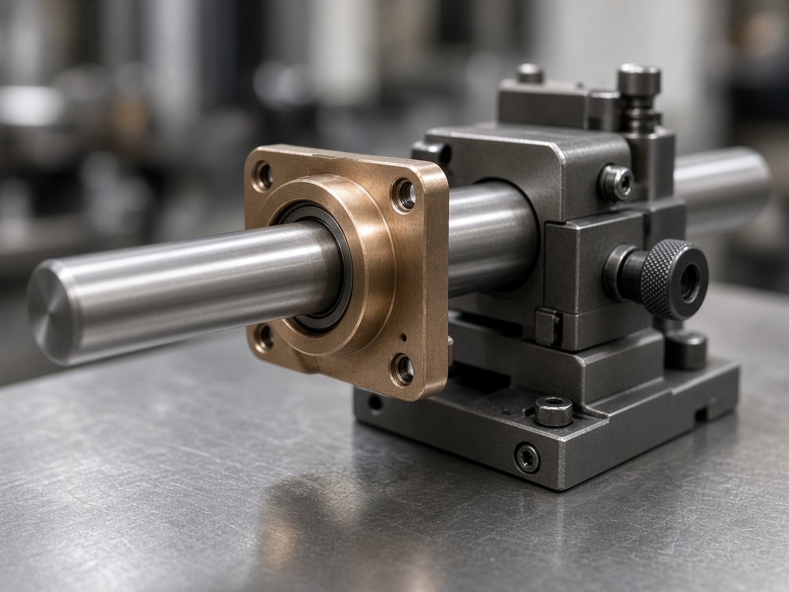
Steel shaft running through a bronze sleeve mounted in a mechanical positioning assembly

02

ILLUSTRATIVE PROJECT

Shaft & flanged sleeve

CNC TURNING

Two mating parts. One common reference.

A sleeve locates on a stepped shaft, with a shoulder controlling its axial position.

PROJECT FOCUS

Mating diameters / shoulder location / bore condition

Read Project Brief

+

Starting information

Both component drawings, the intended fit, datum references and assembly information.

Review priorities

Identify the functional diameters, bore depth and axial dimensions. Confirm the surface condition needed at the mating interface.

Scope to agree

The specified shaft and sleeve, with agreed dimensional checks and protection of mating surfaces.

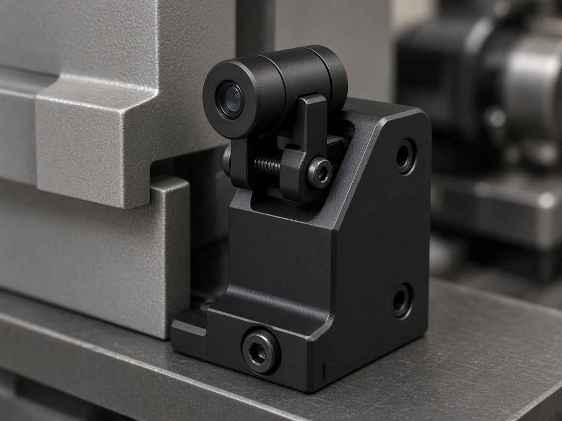
Black finished bracket securing an optical sensor to a machine frame

03

ILLUSTRATIVE PROJECT

Finished mounting bracket

SURFACE FINISHING

A visible finish with protected mounting faces.

An exposed bracket needs a defined appearance while its assembly interfaces remain functional.

PROJECT FOCUS

Cosmetic faces / finish reference / protected areas

Read Project Brief

+

Starting information

The bracket drawing, base material, color and texture reference, and marked functional surfaces.

Review priorities

Separate cosmetic and mating zones. Agree coverage boundaries, final dimensions and appearance acceptance requirements.

Scope to agree

The agreed machining and finish requirements, with suitable separation and protection of visible faces.

YOUR PART MAY CROSS CATEGORIES

A turned body.
A milled feature.
A specified finish.

Include the whole component and its final condition. Off-axis holes, mounting faces and surface treatments belong in the same project discussion.

START YOUR OWN PROJECT

Show us your part.
Tell us what it must do.

Send the model or drawing with the material, quantity and critical requirements. Assembly references and appearance samples can help explain the details.

REQUEST A QUOTE

Tell us about your project.

Regarding: Custom CNC Project

Attach drawings when you send your email.

错误: Content is protected !!