CUSTOM PART MANUFACTURING

CNC Turning Services

Shafts, bushings, sleeves and adapters. Turned diameters and mating surfaces defined around your drawing and assembly requirements.

DESIGNED AROUND THE MATING PART

A diameter on its own
doesn't describe the assembly.

Show us what fits around the shaft, what seats against the shoulder and what holds the parts in position.

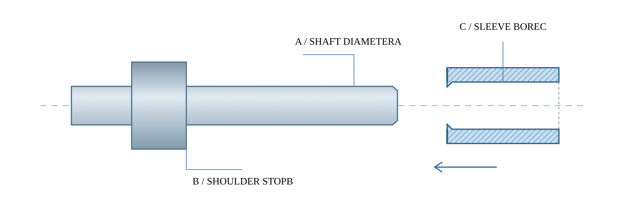
SHAFT + SLEEVE / LONGITUDINAL SECTION

Define the relationship between A and C. Locate the sleeve against B.

Section view · Clearance exaggerated

A

What fits?

Identify both mating diameters and the required fit on the drawing.

B

Where does it stop?

State the shoulder position and the faces that set the axial location.

C

How does it work?

Describe whether the interface rotates, slides, locates or remains fixed.

FOLLOW THE PART ALONG ITS AXIS

From the first face
to the final thread.

Keep the axial relationships on one drawing. A diameter, groove and thread each need a location as well as a size.

01

Establish the reference

Identify the locating face and datum axis used for critical dimensions.

DRAWING INPUT / DATUM REFERENCES

02

Locate shoulders & grooves

Dimension the steps and retaining features from the applicable references. Include mating seal or retaining-part details.

DRAWING INPUT / AXIAL POSITIONS

03

Complete the diameters

Specify stepped diameters, bores and fits relative to the datum axis and locating faces.

DRAWING INPUT / DIAMETER CALLOUTS

04

Complete the connection

Specify internal or external threads, engagement length and seating requirements.

DRAWING INPUT / THREAD CALLOUTS

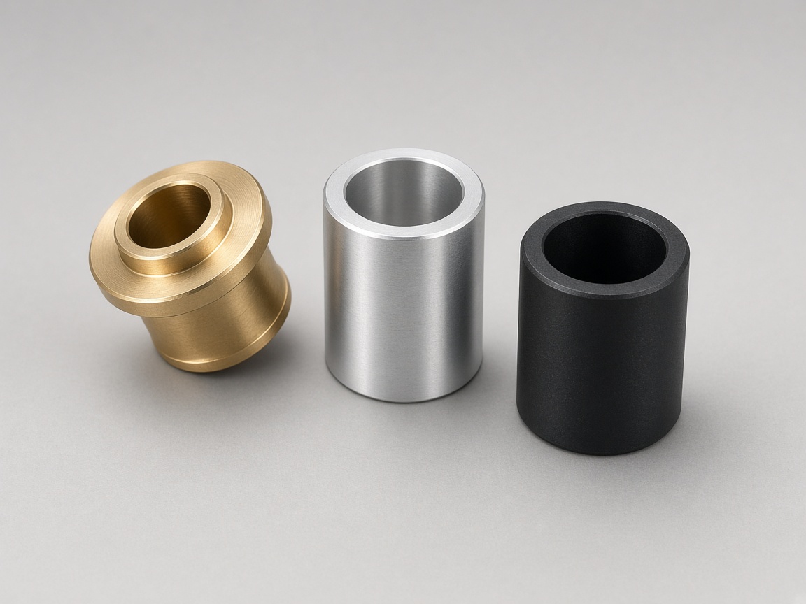
Brass flanged bushing, aluminum spacer and black plastic sleeve

MATERIAL FOLLOWS THE APPLICATION

What will the
interface experience?

Share the material grade where specified. Otherwise, describe the mating part and operating conditions for review.

Include their relationship to the turned axis and locating faces. The complete manufacturing scope can then be reviewed together.

ROUND PART. ADDITIONAL FEATURES.

Flats and cross-holes belong
in the same model.

Include their relationship to the turned axis and locating faces. The complete manufacturing scope can then be reviewed together.

MILLING QUESTIONS

A few details
before you send.

Files, feature limits and finishing requirements for a custom milled part.

Send a STEP or STP model and a dimensioned PDF where available. Include the part revision, material, order quantity, surface requirements and any dimensions that control assembly or function. If only one file format is available, send it with a short description of the part.

Include these features in the complete model and identify any dimensions that cannot change. Tool access, wall support, material and workholding need to be assessed together. Feasibility and any suggested changes are confirmed after drawing review.

Tolerance and size suitability depend on the part geometry, material and machining setup. Provide overall dimensions and mark the critical fits and datums. The quotation confirms the requirements that can be accepted for your specific component.

List the required finish, cosmetic faces, masking, inspection points and documents in the enquiry. These are reviewed as part of the finished-part scope, with availability and delivery requirements confirmed in the quotation.

YOUR NEXT MILLED PART

Send the drawing.
Let’s define the scope.

Share the model and the requirements that matter. Include what is ready now and add the remaining details during review.

01

Drawing & revision

STEP / STP model and a dimensioned PDF.

02

Material, finish & quantity

Include critical fits and your required date.

03

Quotation & next steps

Feasibility, price, lead time and inspection scope confirmed after review.

REQUEST A QUOTE

Tell us about your project.

Regarding: CNC Milling

Attach drawings when you send your email.

错误: Content is protected !!